
Design Spotlight - Biopsy Processing System
The Mission
Many clients for DEKA have developed bleeding-edge cell therapies, but struggle to find methods to reliably scale production to a profitable level. Furthermore, many of these therapies are autologous treatments, utilizing the patients own cells to eliminate the chance of immune rejection. Autologous therapies require a biopsy from the patient that can be impossible to process manually at scale.
The Solution
Our team at DEKA sought to create a turn key solution to this need by creating a universal digestion system that could autonomously process a human biopsy from start to finish in ~1.5 hours with no user intervention (40% reduction from manual process). Systems are intended to run in conjunction to process over 100,000 samples annually.
Note: some aspects of the system may be obscured to protect the intellectual property confidentiality.
System Overview

The universal digester converts a biopsy into a cell solution by adding reagents using a series of pneumatic pumps and valves in a disposable cassette. An enzyme solution is added to the sample, then agitated and quenched before being deposited into a flask as a solution.
Feature Overview:
The bag hanging assembly slides outwards towards the operator, for convenience and to keep operators hands away from heating elements. Compliant clips are a part of the handle to allow operators take the bags on and off 1-handed.
The human machine interface (HMI) is a wipe down compatible, touch screen monitor. The HMI is designed to be an intuitive guide for the operator providing clear and concise instructions throughout the process.
The cassette interface is an easy install solution to keep a closed, sterile system. The pre-assembled disposable cassette is latched into the interface, inserting all pneumatic fittings at once as well as aligning 2 non-invasive bubble sensors.
The sheet metal side panels slide smoothly off the frame and allow access to the electronics and pneumatics panel for assembly and maintenance.
The main vial holder has a circular shaker assembly built into the front face in order to mechanically agitate the solution in the vial. The shaker is surrounded by a flexible gasket that stretches with the shaker to prevent fluid ingress and minimize user pinch points.
The system’s 3 heating elements are located on the bag hanger, flask holder and vial holder. Each heating element is accompanied by an RTD to monitor vessel temperature and a thermal cut-off (TCO) to prevent runaway heater conditions.
The Iterative Design Process
Developments were made constantly from project inception to the delivery of a sleek, user friendly system. This agile development lead to important lessons and allowed for constant feedback from end users to inform future iterations.

Concept 0.0
-
Initial prototype system/technology testing platform.
Total development time: 2 weeks
-
Agile development peg board with tabletop controls array, pneumatic manifold and HMI.
-
Technology showed major promise, particularly in fluid delivery accuracy.
Major improvements required on ergonomics, organization and additional functionality.

Concept 1.0
-
First major development milestone. All required functionality implemented and structural enclosure added.
Total development time: 1 month.
-
System mainly composed of laser cut panels, 3D printed parts and 8020 frame. All electrical and pneumatic components contained within frame and HMI now integrated into front interface.
-
Substantial ergonomics increase and system now completes non-sterile processes with no user intervention.
System lacks safety systems and fail safes required for a lab environment to protect both the user and the product. Aesthetics also need major improvements.

Concept 2.0
-
Final concept level system. Safety systems and ingress protection now present. Major aesthetic overhaul.
Total development time: 3 months.
-
System structure composed of a sheet metal frame and a vacuum formed front. All RP parts were upgraded to machined or injection molded quality.
-
System now consistently completes fully sterile processes with no intervention. Usability/ergonomics at a high level.
System ready for customer feedback.
Pneumatic Manifold
Objective
The purpose of the pneumatic manifold is to provide a dependable and scalable solution for distributing compressed air at four pressure setpoints to actuate the various pumps and valves within the universal digester.
System Requirements
Assembly/serviceability: the assembly must be easy to install and serviced after install.
Compact layout: the assembly must fit in about a 2’ x 1.5’ x 1’ volume.
Modularity: the assembly must be able to expand pneumatic outputs if necessary.
Failure conditions: the manifold must maintain pressure for 15 mins if the system loses power.
Moisture protection: the manifold must protect the solenoids from excess moisture buildup
Design Solution
A sheet metal base was utilized to effectively organize the components and also fit the design within the constraints of the system frame. The sheet metal base also allows the assembly to be easily installed and uninstalled to lend to the assembly and service of the system.
The manifold itself utilizes a modular block system to be able to add more outputs in multiples of 4. As a fail safe, the manifold also has 5 pressure tanks that can maintain the various pressure setpoints for over 30 minutes without power. Finally, a series of PCB boards on the top of the system controls the actuation of the solenoids and relays the signal from the pressure transducers.


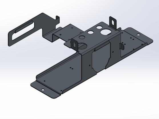

Electronics Panel
Objective
The purpose of the electronics panel is to create a robust and organized structure for supporting the required electronic components. Also within the scope of this design is selecting the appropriate components based on system specifications.
System Requirements
Signal Isolation: The components must be placed in a way as to not interfere with sensor signals.
Compact layout: the assembly must fit in a 2’ x 2’ x 1.5’ volume and fit all necessary componentry.
Organization: The components and their requisite wiring must fit neatly in the assembly.
Failure conditions: the panel must have sufficient ventilation to prevent overheating.
Modularity: the assembly must have room for additional future components.
Design Solution
Two pieces of custom designed sheet metal panels make up the middle and back of the universal digester. Power providing components were isolated on one side and signal components were isolated on the other as to ensure that signals are not disrupted. DIN rails and wire ducts are strategically placed along the panel to accommodate over 30 individual electronic components. Each individual component was thoroughly documented in the PDM and the power draw was calculated to select the appropriate power supply.
A fan is installed in the upper right to draw hot air out of the enclosure and bring cool air through the lower left. Additional press fit (PEM) studs are installed in the back panel to allow for additional DIN rails to be installed in the future.


Cap Leak Test Fixture
Objective
The objective of this design is to develop a reliable, repeatable, and ergonomic leak test fixture for accurately detecting and quantifying leaks in within vessel cap assemblies. The fixture should ensure precision, ease of use, and compatibility with various testing methods
System Requirements
Reliability: the fixture must be able to reliably detect leaks in cap geometry at varying leak rates.
Repeatability: the fixture must consistently create a seal around the inner seam of the cap.
Usability: the fixture must be easy to use and quick to decrease overall test time.
Adaptable: the fixture must be able to be modified to be able to accommodate different caps.
Design Solution
The leak test fixture was designed specifically for vial caps, one large and one small. A cap with a barbed tube is inserted into the fixture and the lid swings close over the tube. The toggle clamp is depressed to compress the gasket and create the seal around the target area. The lid bottoms out on the raised section of the fixture to reliably compress the gasket a specified amount. The tube and cap are then pressurized with a calibrated pressure reservoir (i.e. ATEQ leak test device) to determine if there is a leak and quantify failing results.
The 3D printed body is measured to account for tolerances and sanded to compensate if necessary. Specific pass and fail standards were used to calibrate the leak detection.


